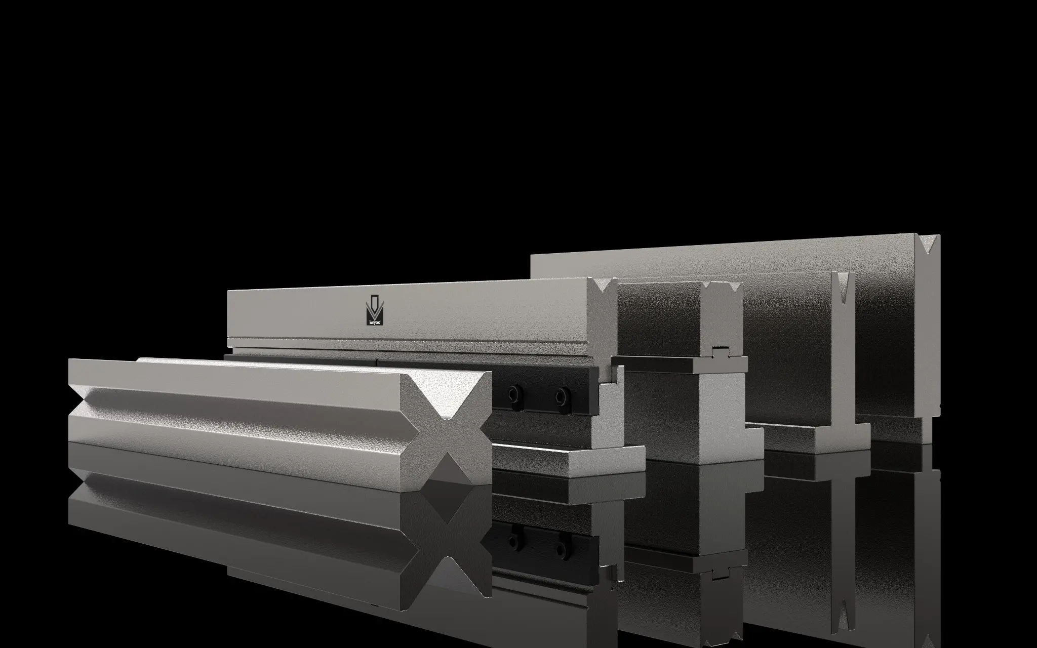
Select press-brake punches and dies from bend method, material, thickness, inside radius, flange geometry, force, tooling load, and the machine's clamping interface.
How do you select press-brake tooling?
Start with the drawing and bend method, then check material, thickness, tensile strength, inside radius, flange length, bend angle, section geometry, required force, tooling load rating, and the machine's clamping interface. Tooling selection is safety-critical: use the tooling supplier's current chart and the press brake manual before production.
Which inputs should be checked first?
| Input | Selection effect | Required check |
|---|---|---|
| Bend method | Air bending, bottoming, and coining use different force and geometry | Approved process plan |
| Material | Strength and ductility affect force, radius, and springback | Material certificate |
| Thickness | Drives die opening, radius, and force | Actual measured range |
| Inside radius | Must be compatible with punch nose, die opening, and material | Drawing tolerance |
| Flange and shape | Can create tool or machine interference | Bend simulation or setup drawing |
| Bend length | Determines total force and load distribution | Longest active bend |
| Interface | Tooling must match the clamp, segmentation, height, and load rating | Machine and tooling specifications |
How should V-die opening be chosen?
For air bending, a V opening around six to eight times material thickness is often used as an initial estimate for common sheet steel. It is not a universal rule. Small openings can increase force and reduce the formed radius; large openings can increase the radius and minimum flange. Use the material- and tooling-specific chart for the final value.
How do you check bending force?
Use the current force chart or calculator supplied for the selected tooling and bend method. Confirm material tensile strength, thickness, V opening, bend length, angle, and safety factor. Check both the press-brake capacity and the maximum permissible load for the punch, die, adapters, clamps, and bed. Never exceed the lowest-rated component.
Which punch shape fits the part?
- A standard straight punch suits many open parts.
- A gooseneck profile provides clearance for return flanges and boxes.
- An acute punch can support acute-angle air bending or a later hemming operation when the process is approved.
- A radius punch is used when the drawing requires a larger formed radius.
Simulate or dry-run complex profiles at low speed. Check the complete bend sequence, not only the first bend.
What should the setup sheet record?
Record the machine, tooling identification, segment layout, orientation, clamp, material, thickness, V opening, punch radius, bend order, force limit, crowning method, backgauge positions, test-piece results, and inspector. Recheck after tooling changes or material-batch changes.
Frequently asked questions
Is V = 8 × thickness always correct?
No. It is only an initial estimate for some air-bending cases. Material, radius, flange, angle, force, and the tooling supplier's limits can require another opening.
Can European-style tooling fit every Metec press brake?
No. The clamp interface and tooling height are configuration-specific. Confirm the exact machine, upper and lower clamps, adapters, segmentation, and load rating in writing.
When is a sample bend required?
Use a sample bend when radius, angle, surface finish, springback, short flange, high-strength material, or complex interference cannot be confirmed from the chart alone.
The Metec Engineering Team reviews machine-selection, process, specification, installation, and operating guidance for Metec sheet-metal equipment.